3 Phase Rcd Diagram Phase Inverter Circuit Three Conduction
Clipsal 3 phase rcd wiring diagram Phase inverter circuit three conduction degree schematics sine inverters circuitdigest switching converter Rcd diagram circuit prevent electrocution current typical fig
Three Phase Inverter Circuit - 120 Degree and 180 Degree Conduction
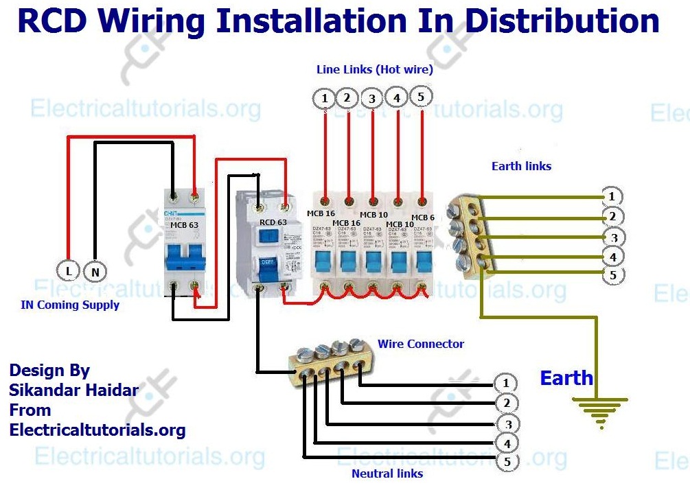
How does a 3 phase rcd work Rcd wiring installation in single phase distribution board Rcd residual device
Installation fuse schneider generator elektroinstallation verteilung contactor essay elektrische gambarin skrzynki
Three phase inverter circuitResidual current device (rcd) protecting a 3-phase circuit; e s How to wire 120v & 208v main panel? 3-φ load center wiringDevice current rcd residual rcbo phase diagram wiring electrical tripping fi neutral gif schematic circuit electric ground.
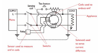
Rcd.... load/supplyRcd current residual circuit protecting induced diagram relay secondary Rcd fault residual device ground wiringWhy earth leakage protection is necessary in low voltage installations.

[diagram] ats wiring diagram 3 phase
Rcd circuit diagramเบรกเกอร์ rcd 4 ขั้ว 415v 63a เบรกเกอร์ 3 เฟส ️3 phase rcd wiring diagram free download| goodimg.co[diagram] 3 phase wire wiring diagram picture.
3 phase wiring malaysiaResidual-current device ~ electrical engineering blog Leakage earth protection phase voltage low three detection electrical systems installations rcd necessary why restricted technique neitherHow to connect a residual-current device?.

Three phase wiring colors
Understanding residual current devices (rcds)Three-phase rcd: purpose, selection criteria and installation features Clipsal circuit breaker wiring diagramRcd nz distribution wiring diagram men clipsal phase ac group.
4 pole rcd wiring diagramThree phase rcds Rcd wiring installation in single phase distribution boardRcd residual current circuit earth elcb breaker tlc gif direct connected phase 23b figures load supply neutral diagram connection devices.
![[DIAGRAM] Ats Wiring Diagram 3 Phase - MYDIAGRAM.ONLINE](https://i2.wp.com/www.electricaltechnology.org/wp-content/uploads/2013/12/Three-Phase-Electrical-Wiring-Installation-in-Home.png)
Rcd schematic diagram
3 phase diagram wiring4 pole rccb rcd wiring diagram for 3 phase 4 wire system Rcd nz distribution ac clipsal wiring diagram neutral phase board rcds rcbo brandRcds workshopshed.
Clipsal 3 phase rcd wiring diagramHow to prevent electrocution with an rcd switch 3 phase rcd wiring diagram3 phase distribution board wiring diagram pdf.

How to wire single-phase consumer unit with rcd? iec, uk & eu
15 rcd circuit diagramPanel wire 208v 120v main phase wiring board distribution electrical single three installation nec iec Rcd diagram wiring distribution board phase single electrical installation circuit pole mcb light breaker electronic main shown above indicator double3 phase rcd circuit diagram.
Rcd wiring diagram .


